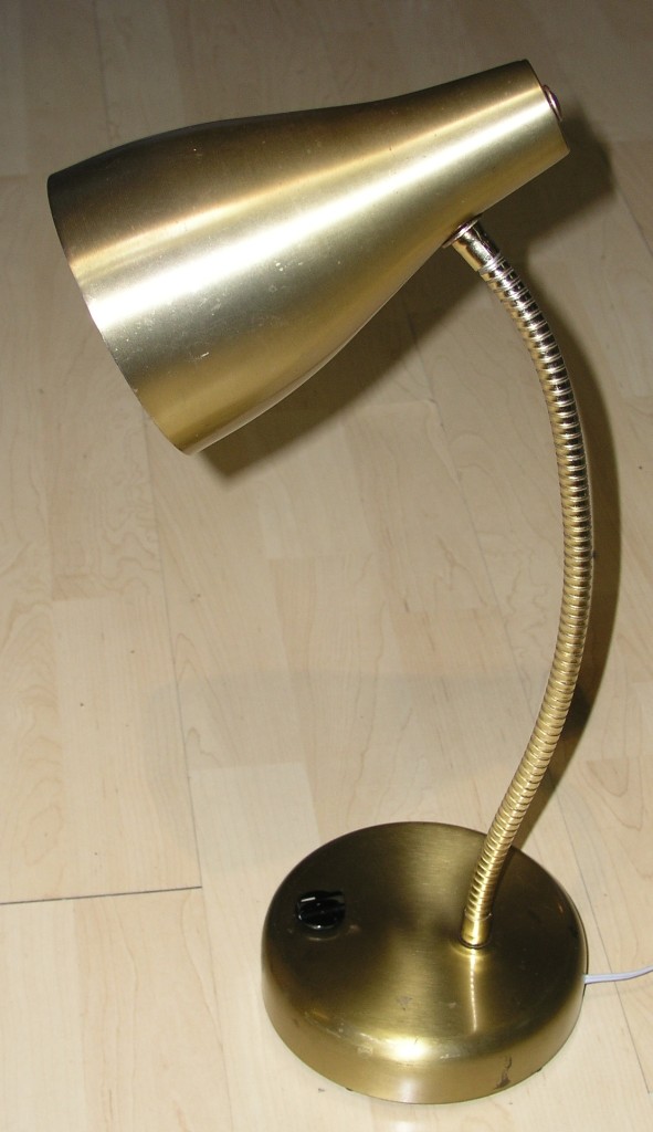
I did a quick Christmas present for my brother. He found this old lamp and I converted it to LED with a micro-controller to do PWM dimming.
 The underside. Control knob at right is read by the Arduino Pro mini at left. Transistor at top of circuit board forms a constant current source with current set by large rectangular resistors and is switched on and off to do PWM by the Arduino.
I machined this aluminum to provide a mount and heat sink for the LED.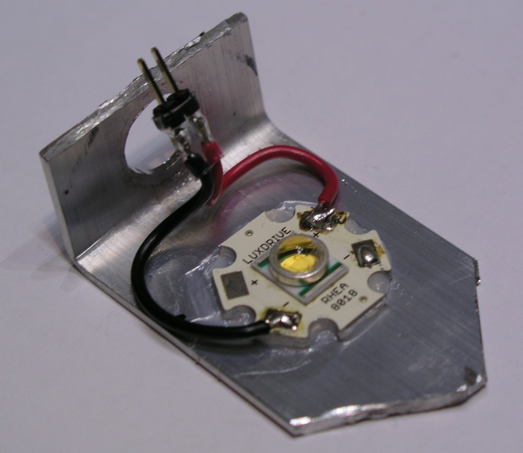
 The schematic.
The Arduino reads the voltage on A0 from the potentiometer R2 and outputs a PWM signal on D10. Q2 burns excess voltage because its gate is controlled by Q1 which is sensing the current flowing out of Q2 through R3 forming a feedback loop. The PWM signal is also connected to the gate of Q2 adding its signal to Q2’s output.
LED driver portion inspired by this instructable by dan at MonkeyLectric.